2 issues i see
1) your not connecting up all the 12V lines. there are total of 5. so it may still pull power from the motherboard.
2) path of least resistance... between getting power from motherboard or from the molex connector the difference in resistance is very small.
possibly measurable in milliohms. so it may still pull power from the motherboard.
I'm no electronics technician so i can't say for sure.
but i do know that hen i physically cut the ribbon wire and plug the 12v wires into a molex connector i am for sure not drawing any power from the motherboard.
Did I ever say I wanted to prevent power from being draw from the mother board?? Nope, didn't. You're living in a ridiculously paranoid world if you're worried about drawing any power through the mother board, its just plan silly to avoid it entirely, and you gain absolutely nothing from avoiding it, need I repeat, NOTHING. The PCI slots are designed to provided power for pci cards, so if you create additional pathways for current to flow then you will lower the amount traveling on each pathway, thus in turn increasing to total amount of current able to be drawn w/o damaging components ( traces and wires ); its really a pretty basic concept, re-read the articles I posted,
http://tinyurl.com/aynwg http://tinyurl.com/5s5llfohave you ever check these pins A2 & A3, B1, B2 & B3 for continuity ?? They are all connected on the cards PCB - all the the same copper pad. I can assure you that by isolating those 5 wires and detaching them from the riser / mobo entirely and reducing them to 1 - 16awg wire you are in fact decreasing the amount of current carrying capacity. You would be so much better off just leaving them connected to riser and the mother board and just have an additional 12v molex at your disposal. All Wires can be though of as resistors, b/c they all have some inherent amount of resistance.
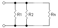
Resistors in Parallel
http://upload.wikimedia.org/wikipedia/commons/2/2a/Resistorsparallel.pngIn a parallel circuit, current is divided among multiple paths. This means that two resistors in parallel have a lower equivalent resistance than either of the parallel resistors, since both resistors allow current to pass. Two resistors in parallel will be equivalent to a resistor that is twice as wide:
http://upload.wikimedia.org/wikibooks/en/math/3/7/6/3760f431a4d755d2181151b4046d80a7.pngSince conductances (the inverse of resistance) add in parallel, you get the following equation:
http://upload.wikimedia.org/wikibooks/en/math/b/7/d/b7d797059343dbd0d2f8f8d09b06f1c2.pngFor example, two 4 O resistors in parallel have an equivalent resistance of only 2 O.
To simplify mathematical equations, resistances in parallel can be represented with two vertical lines "||" (as in geometry). For two resistors the parallel formula simplifies to:
http://upload.wikimedia.org/wikibooks/en/math/b/2/2/b22693aac2a2de84160944e7f0ee4fec.pngAnother useful read
http://tinyurl.com/3u5crbb"Electrical resistance
Voltage can be thought of as the pressure pushing charges along a conductor, while the electrical resistance of a conductor is a measure of how difficult it is to push the charges along. Using the flow analogy, electrical resistance is similar to friction. For water flowing through a pipe, a long narrow pipe provides more resistance to the flow than does a short fat pipe. The same applies for flowing currents: long thin wires provide more resistance than do short thick wires. "
Also,
2 issues i see
1) your not connecting up all the 12V lines. there are total of 5. so it may still pull power from the motherboard.
2) path of least resistance... between getting power from motherboard or from the molex connector the difference in resistance is very small.
possibly measurable in milliohms. so it may still pull power from the motherboard.
1) *face palm*
2) Pins B10, A9 & A10 pull power through the mother board, so better pull those too
3) 1 milliohms = .001ohms
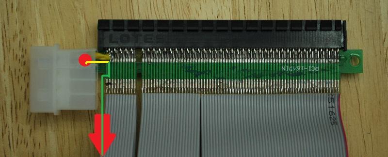
In the image below
Red indicates power source
Yellow Line = .3 ohms
Green Line = .3 ohms
Yellow & Green Line = .2 ohms
point - less resistance
http://image.bayimg.com/lakggaadh.jpgAnother thing,
Notice how in this picture all the lines are intact and the molex is just soldered to one side of the board.
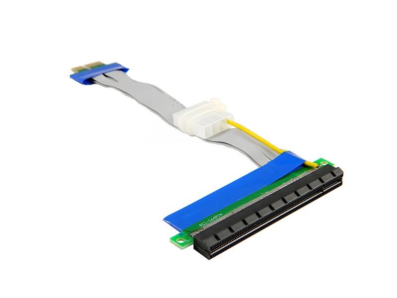
http://image.bayimg.com/fakfhaadh.jpgIn any case the additional molex is just there to as a supplemental power inclusion point - not a replacement for all power going to the edge card ( pcie end that is )